Here is the resource that I found yesterday to explain it properly: Pulse Shaping with raised cosine filters.
I found it confusing at first for two reasons. The first is that I didn't know if Wikipedia's formula was for time or frequency domain, and the second is that I had no idea that the RRC is centered on each PSK symbol, meaning that a time of 0 is the center.
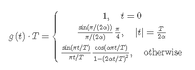
Here is the time-domain formula from the University of Stuttgart's Webdemo (linked above):
[REF] Stephan ten Brink, "Pulse Shaping," webdemo, Institute of Telecommunications, University of Stuttgart, Germany, Aug. 2017. [Online] Available: http://webdemo.inue.uni-stuttgart.de
Why to use it
If I told you to multiply a square wave with a cosine and sine wave to make a QPSK signal, you'd get a result similar to the top stereo track shown below.
Those are some sharp transitions. This is what I got when I first tried to make my own QPSK signals. It seems well and good, right? We have our digital wave mixed with I (cosine) and Q (sine) to make an IQ signal playable in an SDR program. Well, yes, but there's a slight problem...
[Vertical is frequency, horizontal is time]
This isn't what QPSK is supposed to look like. See all the spurious signals splattering everywhere? Satellites like Inmarsat have neat and narrow QPSK, so why does mine look so bad?
It turns out that we've simply placed a square wave (which is full of harmonics) into the RF spectrum by mixing with a carrier.
Now, notice the bottom stereo track. It is the same QPSK signal, but smoothed out using a root-raised cosine filter.
Notice how narrow it becomes:
The signal is also good enough that Signals Analyzer can lock onto the 80 kBit bitrate:
I initially made the mistake of entering 40000 in the BR (bitrate) field because it's 40 kHz QPSK, and with QPSK the bitrate is twice the symbol rate.
(Below) SA can also lock onto the bitrate of the unfiltered QPSK, which means that although it's undesirable for transmitting, it is nonetheless a valid signal (although I did have to zoom out the bottom-left constellation window a bit).
How to use it
The formula generates "taps", which means an array of values to be used on the signal you want to process. In our case, we multiply the taps by our signal.
Here are the variables:
t: time, in fractions of a second, since the center of the symbol.
T: length of half a symbol, in seconds (1 / (2*symbol rate)). (Why not 1/symbol rate? Pitfall explained below)
alpha: roll-off factor, ranges from 0 to 1 (1=wide, 0=brick wall filter)
To maintain the parameters of the signals shown earlier, let's assume we want a QPSK signal with a symbol rate of 40 kHz (80 kbit/sec) and we'll have it in an IQ file sampled at 1 MHz.
Our variables would be:
t: x/sample rate (in our case, x/1000000). x is the FOR loop variable.
T: 0.0000125
alpha: 0.1 (very high roll-off)
40 kHz is a convenient value since we want an odd number of taps. Since 1,000,000/40,000 = 25, it will take 25 samples to make one symbol and so we need 25 taps.
The center value will be 12 (base 0) or 13 if you prefer base 1. We want to start at 0 so we can do our time values properly, so we want a FOR loop to go backwards from 12 to 0.
Pseudocode:
---------------------------------------
for (x = 12; x >= 1; x--) {
taps[12 - x] = [The formula depicted above, substituting (x/1,000,000) for t]
}
taps[12] = 1
for (x = 1; x <= 12; x++) {
taps[12 + x] = [The formula depicted above, substituting (x/1,000,000) for t]
}
---------------------------------------
This code will give you 25 taps. Think of it as a matrix with just one column; you would use matrix multiplication to multiply each point by a corresponding point in time on an unfiltered QPSK signal. Just make sure to align this so that the taps begin at the beginning of the QPSK symbol, otherwise it won't filter properly. Here's a crude ASCII drawing of what I mean:
| Taps | | QPSK |
| Matrix | * | IQ |
| | | samples |
Note that both matrices are only ONE symbol long; the taps repeat at the start of each symbol.
Pitfall
The pitfall I was referring to is that 0 is the center. This is what my first RRC taps looked like when I calculated starting from 0:
I mistakenly thought that was the whole filter but it's only the right half. Again, here is the right half of another RRC filter:
This is why we use 1/(2 * bitrate). If you use 1/bitrate, then the right half will span the entire symbol time when you only want it to span half. With 1/(2 * bitrate), each half will cover half the symbol.
I hope this helped if you had no idea how to program the RRC. Use the comment section below if you have any questions or if I left something out.


No comments:
Post a Comment