Thursday, December 29, 2016

5ft (1.5m) Satellite Dish

A few days ago I constructed a crude 5-foot satellite dish and it got decent signal strength from Inmarsat 4F3 (98W) while indoors. Today I took it outside to finish testing it.


Inmarsat Aero from 98W using my 80cm DirecTV dish:


Same LO frequency, 5ft dish
Admittedly, the SDRplay's oscillator drifted a bit.


Using the bigger dish, you can clearly see how the wide signals are redder and how the narrow ones are appearing.

I was also, using my big dish, able to receive the Inmarsat satellite at 54W, which I have never been able to receive previously when I was using the 80cm dish.

Inmarsat 54W Aero reception, 5ft dish


Finally, I noticed that some of the Aero signals seem to be almost mutually exclusive. As I moved the helix in front of the dish, some would fade out while others faded in.


Except for the bottom, they do appear to be mutually exclusive, as if there was some kind of polarization difference or something.

Tuesday, November 22, 2016

Verizon 1x Voice/SMS 24-hour Traffic Waterfall

My last long-term waterfall post was about the double CDMA2000 signal near my house. After more reading, I'm convinced that it's 3G EV-DO (data only). The voice and texting signal is completely different. In that last post I thought the signal carried voice and texting and was surprised to see the activity pick up late at night, but someone told me that it must be phone updates, which would make sense for 3G data. Yesterday I started a 24-hour waterfall of the CDMA 1x signal near my house.

I wanted to know which network I was receiving, so I checked both Verizon and Sprint coverage in my city. Verizon covers the whole area while the nearest Sprint service is 7 miles away and the next closest coverage zone is 20 miles away. Guessing based on the incredible Verizon signal strength reported by an old flip phone, this signal must be Verizon.

Just like last time, I disabled Tuner AGC so we could see the tower's dynamic power changes. I also had trouble with the DC spike, so I used the SDRplay's options to get rid of it. I could've used HDSDR, but I may want to record this sometime and HDSDR doesn't apply its IQ compensation to recordings, so it's good to know how to do it in hardware.

This waterfall spans 24 hours, from November 21, 2016 at 9:17 PM to 9:17 PM the next day. Each vertical pixel represents 1 minute, +/- 1 or 2 seconds. Center frequency is 874.8 MHz. Waterfall bandwidth is 2 MHz with a signal bandwidth of about 1.25 MHz.


Sunday, November 13, 2016

Radio sounds in music

I noticed that certain music contains sounds you'd recognize if you do SDR.

1. ItalyCable excerpt ≈ some Japanese song

On May 27, 2015 I was using a WebSDR and heard an unfamiliar time station called ItalyCable on 10 MHz. It played some really nice music so I took a recording. I saved it but forgot where and thought I had deleted it, but today I found it in a DriveImage XML hard drive backup. The recording was taken around 3 PM Eastern Daylight Time, although you should be able to pick out the UTC time if you understand Italian.


Why is this significant? Because I recently heard an obscure Japanese song that sounded quite similar (below).


(Below) Not as cool, but something to mention:

2. Intro and chorus of Kiiara's "Gold" ≈ encrypted police walkie-talkies

It's not exactly like police radio because while the speech is scrambled, the tune accompanying it makes sense. See the video: https://www.youtube.com/watch?v=sO9cBXRcBvo


Sunday, November 6, 2016

Fixing Commotion internet radio on Windows XP

I've been busy lately so it's hard to find time to write posts. I've managed to look over some C# code by Lucas Teske and write a low-pass filter for my Java Costas loop. I did get some cool output in Audacity that looks kind of like digital symbols at the beginning.


What I'm mainly writing about, however, is a quick hack I learned about Commotion Internet radio. I wanted to listen to a station called Way FM on my Windows XP computer, but it wouldn't work in Opera or IE. The page remained silent without giving any errors. I was able to make it work on my Windows 8.1 tablet (Opera), Windows 7 x64 PC (Opera), and ZTE Sonata phone (the app), but it stubbornly refused to work on Windows XP. Using a mobile phone or tablet to listen was the only convenient way but it required keeping the screen on, which in turn usually means staying plugged in, which is hard on the battery, so this was not ideal.

I kind of knew that it was because Opera for XP won't play MP3 for some reason. I've had trouble on websites with HTML5 embedded MP3's and had to download them to hear them. I did an unsuccessful Google search about this problem with Commotion Internet radio so I looked at the page source and expected to have to find a weird JavaScript streaming system. I was surprised to see an API Key field near the top, which indicated player code, and even more surprised to find the field underneath that contained a plain MP3 URL, which I copy-pasted into Media Player Classic and was able to listen to. It will sometimes buffer and even pause, but that also happens on the webpage.


I was concerned that this MP3 issue was a nail in XP's coffin, so this fix was fortuitous.

Monday, October 17, 2016

Charting cell tower activity

I wondered if cell tower activity slopes off during the night so I did a long-term waterfall using the method I described previously. I figured that since people do most of their talking, texting, and moving around during the day but leave their phone by their bed at night, there should be significantly less dynamic power change on the downlink as it gets later.

I chose half of the CDMA signal near my home, one of the ones Ywsia1 says has little activity. I also disabled the AGC so my SDRplay would not keep compensating on the gain reduction.

The picture below spans from 11:51 AM on Sunday, October 16, 2016 to 4:10 AM the next day with the usual 1 vertical pixel = 1 minute, with +/- <1 second accuracy.


Here's an annotated version:


To my surprise, the day did not show much activity but things really heated up from about 11:48 PM to 1 AM.

Thursday, October 13, 2016

Info on IS-95 (cdmaOne)

IS-95, I'm told by several sources, is one of the signals I've seen and which is half of the double signal provided on my cellphones page. Recently I did some reading on the standard. It turns out it was the predecessor of CDMA2000, which a lot of modern phones use. You may notice if you have a Verizon phone that the Internet will go out and the top bar will say "1X" when a phone call is in progress. That's your phone dropping 3G (or 4G) and switching down to CDMA2000 to make or receive the call. My phone, however, is on Cricket and switches down to 4G from LTE when I make calls.

IS-95 looks easy to decode because it only uses QPSK, never QAM. I found an interesting college lecture on the standard: http://www.pitt.edu/~dtipper/2720/2720_Slides9.pdf.

You'd think that IS-95 networks would have been shut down long ago, but like analog cell phones they may be required by law to keep the networks going until the FCC decides, or maybe enough people still use 2G phones that it's worth it.

When I contributed the first 3G signals on sigidwiki.com, Ywsia1 was quick to identify them and noted that he couldn't hear much traffic being handled (you can tell if you use AM). That's understandable, considering how far out I live, so when I was near Hanahan recently I recorded about 2 minutes of what appears to be IS-95. Look at an excerpt from the PDF linked above:


When I measured the bandwidth of the vast majority of the energy contained in the signal, it spanned from 862.281 to 863.509 MHz. That's 1.228 MHz! You can find a copy of this signal on the cellphones page.

When I recorded the sample I used slightly more amplification and aimed the antenna better, so if you measure the width you may come up with a little more. However, when the signal wasn't so strong, most of the energy was indeed contained within precisely 1.228 MHz.

[Update 10/14/2016]

CDMA2000 is considered 3G while IS-95 is 2G. I wondered if any modern phones could use IS-95, and I think I found a recent one on Amazon that can. Notice how it specifies both 2G and 3G CDMA.


----


I learned that a Costas Loop is instrumental in demodulating QPSK, so I spent a while yesterday trying to put one together. I took a 1200-baud Inmarsat signal and saved it into a 4800Hz wave file (pictured below).


Then I watched a YouTube video that explained the Costas Loop. I wrote a Java app that would multiply the I and Q channels by 2cos(ft) and -2sin(ft), respectively.

Once that was done, I combined the 2 channels back into a wave file and played it in HDSDR. I now had 2 peaks, one at -1200 Hz and another at 0 Hz. I was initially excited, thinking that the -1200 Hz peak meant I had guessed the rate on the first try and my program had found something, but I now think it may be entirely generated by the program and that the peak would be at any frequency I had entered.

Anyway, the next step is to low-pass filter the output so you don't get the high mixer product. I didn't know how to low-pass outside of Audacity so I skipped that step and just opened the resulting wave file in Audacity. I used the Nyquist command (mult (aref *track* 0)(aref *track* 1)) to multiply the tracks by each other and see if any error signal would show up. To my surprise, both tracks became completely zeroed out. I wondered how that could be, so I did Undo, amplified the original tracks, and then re-did the Nyquist. This time, it stayed flat for almost the whole file and then slowly ramped up. Click to enlarge.


This seems like a slowly-increasing error signal, but I couldn't be sure because I had skipped the low-pass step. Today I used Audacity to do that. I amplified first, then tried to do a 2400 Hz lowpass filter, but it told me that was impossible since my file was 4800 Hz. Then I realized that I had to enter 1200 Hz. After that I used the Nyquist command to produce the error signal and got this:


Here is the "error signal" both amplified and zoomed in:


There was a huge peak in the original file, so I don't know that that matters much.

Wednesday, September 21, 2016

Centering (downmixing) a signal

Ever want to record a signal but your SDR just didn't have a suitable bandwidth? That's an issue on the SDRplay. If you have a 2.5 MHz signal, for example, the least bandwidth you can use is 5 MHz. That's a lot to record when you just want one signal. And what if you need to use large bandwidth to offset the signal from the center so the DC spike doesn't mess it up? The DC spike can be a huge, almost insurmountable problem in the GHz bands. See the picture below.


Apparently if you record as a WAV and open with Audacity, you can multiply both tracks by a sine wave to shift an off-center signal to the center. However, I don't know how you'd do this for a signal on the left since Audacity doesn't accept negative values.

Here's how it's done, based in part on advice from Steve the Fiddle on the Audacity mailing list:

  1. Open your IQ file
  2. Split it to mono and remove the right track
  3. Create a mono track and generate a sine wave of the desired frequency
  4. Make Stereo Track
  5. Open Nyquist Prompt and run this:
  6. (mult (aref *track* 0)(aref *track* 1))
  7. Remove one side (both will be the same) and save as a mono wav file.
  8. Repeat with the right channel.
  9. Open a new Audacity project and combine the 2 files you just created.
  10. (Obvious) The original left channel (I) must be the left channel in the resulting file, and the same with the right channel (Q).
  11. Finally, see that it worked using HDSDR or something similar.


This is what it looked like when I used a 550 kHz tone. You can see that it's not perfectly centered because 550 kHz was not quite right, but it's very close.


Seeing the double signal, I initially thought I had created a lower sideband but upon closer examination I saw that it was not mirrored like AM should be, but rather duplicated, so this apparently works. You can see the faint carrier at both plus and minus 550 kHz along with the higher, non-mirrored duplicate of the signal.

I then low-pass filtered in Audacity (Effect->Low Pass Filter) to 900 kHz to get just the desired signal.


Now it's much easier to see how off-center it still is. Finally, here's a picture of this in SpectraVue:


This has significant implications not just for analysis but for saving space on IQ recordings.

Monday, September 12, 2016

1st Anniversary Post

Yesterday was a full year since I discovered how to decode HTDV on the SDRplay. While I couldn't think of anything cool to publish yesterday, I did take my SDR setup with me today. I live out in the country where very little happens and wanted to see how much was going on in the city. My first test was on the 3rd floor of a building. I had trouble seeing any 3G towers (even my new 4G phone reports 1 bar at times around here), but I did see an unfamiliar walkie-talkie protocol called Cap+, which DSD+ can mostly decode. I barely made out some people talking about Highway 17 and LED traffic cones/markers. After I got VB Cable running and the audio levels good, I was able to hear conversations between employees of a pest control company. It was about 9:24 AM when I got it working well, and I heard a worker say he'd be late for his 9:15 appointment and ask the office to call the customer and let her know. However, I did not get any noticeably better reception from being 3 stories up. I couldn't even get more than a faint trace of NOAA radio.

Later I went to a library (only 2 stories but with more comfortable sitting areas) and was able to get what I strongly believe is a 3G signal along with something a little lower that may be GSM.


Measuring crudely, the wide one is 3.9 MHz which is close to the expected 3.84 MHz of a 3G signal. Wikipedia also reports that the downlink band in question spans 1930 to 1990 MHz, and it looks like these are skirting the bottom edge.

I'm still hard at work studying DSP in my spare time. I found a bug in the Python scripts I released. I shouldn't have used the radians() function. That t variable in sin(2*pi*f*t) was just time, not time as degrees.

While there's not much I can currently do on the cell phones project, I can still take IQ recordings and add them to the cellphones page. Taking my equipment in public today has allowed me to record some 2G GSM, which I don't really have where I live.

While I may never be able to get much from a cell phone downlink, I hope to at least see some indication that I'm close, even if it's just a PSK/QAM constellation. So far the chances are looking slim, but I'm not too discouraged because this is how the HDTV experiment began. At that time I had searched for months without success. It really looked like there was no possible solution to watching TV on the SDRplay, but I wouldn't accept defeat. Of course I am realistic and if the TV issue had been a hard limit in the SDR's chips then I would have quit. I only continued because I could see that it just needed a software solution.

Anyway, my efforts ended up paying off and I'm surprised at how popular my TV post continues to be. It shows that almost anything is possible with enough effort. I hope my cellphones/3G project will be just as rewarding.

Friday, September 9, 2016

Update: AM in Quadrature

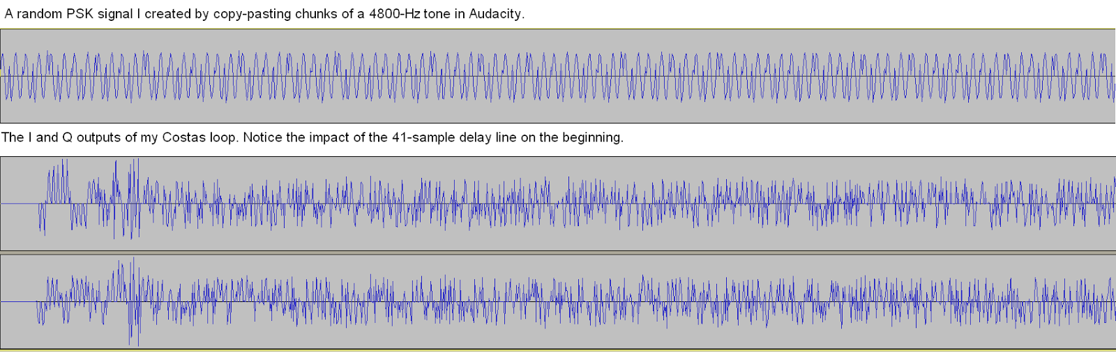
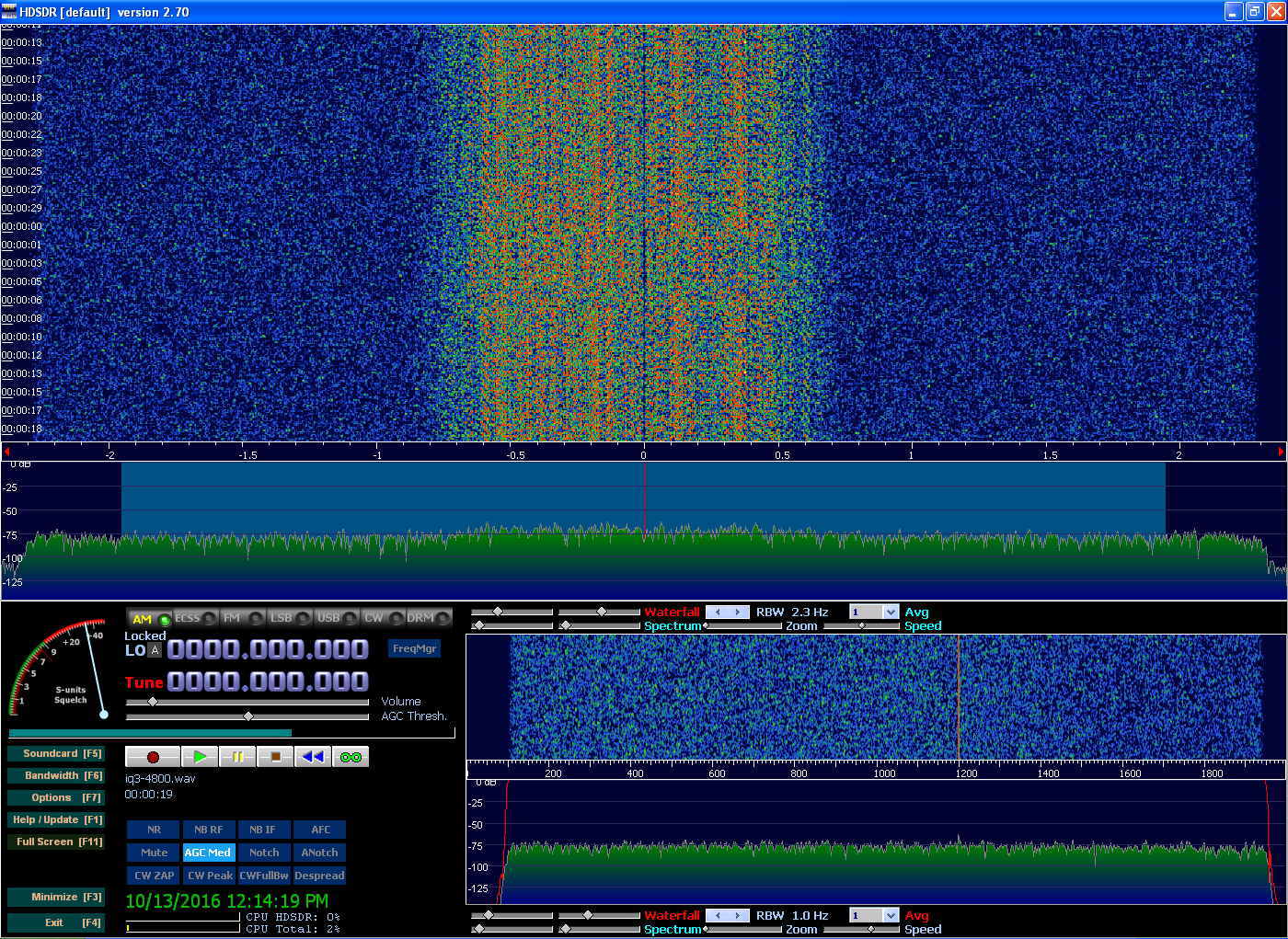
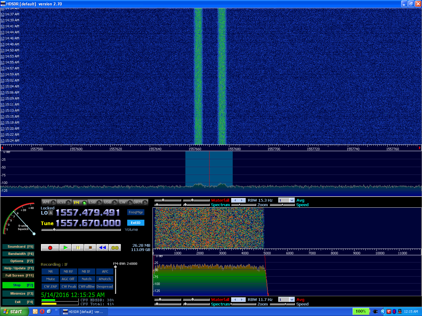
I wrote a new version of my AM modulator that does quadrature. When you use a plain cosine wave (f(x) = cos(x) rather than f(x)=cos(2*pi*freq)), it makes a carrier that is almost at 0. Suppressed-carrier mirrored audio is always present in the center of my quadrature output, and it corrupts the desired signal if you don't modulate it onto a higher frequency than 0, as pictured.


You may be asking, why cosine? Because I saw that the waveform of a sine is 90 degrees ahead of a cosine, and unless I'm mistaken the Q should come 90 degrees after the I. Using I=sin and Q=cos, it was backwards. Yesterday this drove me crazy until I realized and corrected the mistake in the script.

It makes the difference of which side of 0 the signals end up on. Here's a picture of how it should look:


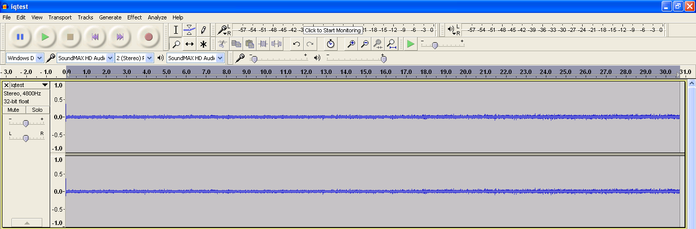
Something I noticed is that if you increase the frequency value inside the script then the output sin/cos waves will look distorted in Audacity. However, the audio demodulated by HDSDR sounds great either way, so it's not distorting much.

Wave when f=2


Wave when f=12


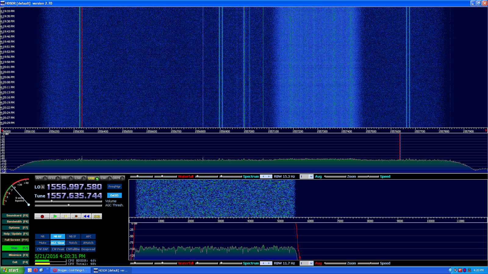
I also found an interesting relationship between frequency (the f in sin(2*pi*f)), the file's sampling rate, and the resulting signal center frequency.

The original audio file was 48 kHz and so was the quadrature output since the script copies the headers. When f=12, the AM signal's center frequency was about 10.1 kHz. When I fed the script a copy of the audio that was upsampled 4x to 192 kHz, the center frequency became 40.2 kHz. Changing f from 12 to 2 while keeping the 192 kHz rate made a precisely 6.7 kHz signal. In the case of 192 kHz that means (center_frequency / f) = 3.35.

In the case of 48 kHz, the constant is different. I generated a file with f=2 and a rate of 48 kHz to see the constant. In this scenario, the carrier wasn't on an easily readable frequency boundary, so I set RBW to 0.2Hz and zoomed in fully. I estimated it to be 1.675 kHz.


Well, it turns out I was only 8 Hz off. Rearranging the formula above: if constant = (center_frequency / f), then

centerfrequency = constant * f

With 48 kHz, the constant is 0.841667, so the center frequency is 1.683 kHz.

And one more relationship to tie it all together: notice how the constant for 192 kHz is close to 4x the constant for 48 kHz. So close, in fact, that we can approximate this:

constant(sampling_rate) = ~0.0175 * sampling_rate

where sampling_rate is kHz, not Hz. However, note that this is an approximation for estimation purposes and is NOT as accurate as the f versus center frequency constants.

Finally, here's the Python script used to generate everything illustrated here. It makes separate I and Q mono WAV files which you must put together as left and right stereo channels, respectively.

------------------
import math

def radians(degrees):
    return (degrees/360)*2*math.pi


#plt.axis([0,1000,0,255])
#plt.ylabel('some numbers')
samples=1000000
x=[]
i=[]
q=[]
multiplier=[]
demod=[]
amp=1
freq=2 #1/8
phase=0
for d in range(samples):
    x.append(d)
    #y.append(amp*math.sin((2*math.pi*freq*radians(d))+phase))
    sinwavevalue=math.sin(radians(2*math.pi*freq*d))
    coswavevalue=math.cos(radians(2*math.pi*freq*d))
    i.append((coswavevalue/2)+0.5)
    q.append((sinwavevalue/2)+0.5)
    #multiplier.append(amp*math.sin((2*math.pi*freq*radians(d))+phase))

#for element in range(len(y)):
    #demod.append(y[element]*multiplier[element])
#plt.plot(x,demod)
#plt.plot(x[0:1000],y[0:1000])
#plt.show()
bytepos=0
with open("D:/time8a.wav","rb") as infile: #Input File
    with open("D:/time_am_f2_i.wav","wb") as o: #Output file
       
    #byte = i.read(1)
        for idx in range(0,44):
            byte=infile.read(1)
            o.write(byte)
       
        while byte:
            bytepos +=1
            if (bytepos == samples):
                break
            test=float(float(int.from_bytes(byte,byteorder="big"))*i[bytepos])
            #test=float(127*i[bytepos])
            #print(int.from_bytes(byte,byteorder="big")," * ",y[bytepos]," = ",float(float(int.from_bytes(byte,byteorder="big"))*y[bytepos]))
            tmp = [int(test),]
            #print(bytes(tmp)," (",int(test),")")
            o.write(bytes(tmp))
            byte = infile.read(1)


bytepos=0
with open("D:/time8a.wav","rb") as infile: #Input File
    with open("D:/time_am_f2_q.wav","wb") as o: #Output file
       
    #byte = i.read(1)
        for idx in range(0,44):
            byte=infile.read(1)
            o.write(byte)
       
        while byte:
            bytepos +=1
            if (bytepos == samples):
                break
            test=float(float(int.from_bytes(byte,byteorder="big"))*q[bytepos])
            #test=float(127*q[bytepos])
            #print(int.from_bytes(byte,byteorder="big")," * ",y[bytepos]," = ",float(float(int.from_bytes(byte,byteorder="big"))*y[bytepos]))
            tmp = [int(test),]
            #print(bytes(tmp)," (",int(test),")")
            o.write(bytes(tmp))
            byte = infile.read(1)

Thursday, September 8, 2016

Homemade AM modulator

I recently got into Python and wrote an AM modulator. I learned the idea from a free PDF called Think DSP. The concept is really simple and just involves multiplying audio samples by sine wave samples. It was a bit difficult where I had to cast bytes into floats and then back again. This is a no-brainer in Liberty BASIC, but I stuck with Python and got it working the same day.

I have previously tried to write processing software for sound but failed. I thought the sound samples might be a weird logarithm that must be undone, but during this project I saw that sound is intuitive to work with and produces the expected results if you use 8-bit unsigned WAV. Being unsigned, it gives you values from 0 to 255, which really is simple to manipulate, and Audacity will show the expected waveform when you open it.

My Python script takes an input wave file and multiplies 100,000 samples by a sine wave. To save the trouble of having to use Audacity's Raw Audio import feature, the script copies the WAV headers to the new file. The output audio length therefore isn't accurate but Audacity and HDSDR have safeguards to avoid reading too far.

Here's the resulting output in HDSDR.


One more thing before I share the script: this is a mono WAV file, which is why HDSDR's frequency scale starts at 0 on the left. I tested with a stereo 8-bit WAV and HDSDR considers it to be IQ and centers 0 on the frequency scale, with negative and positive frequencies on either side. This is good to know for when I start generating quadrature signals. 


And now the script:
-----------------
#import matplotlib.pyplot as plt
import math

def radians(degrees):
    return (degrees/360)*2*math.pi


#plt.axis([0,1000000,-1,1])
#plt.ylabel('some numbers')
x=[]
y=[]
multiplier=[]
demod=[]
amp=1
freq=18 #18 corresponds to 15.075 kHz in this case (see picture above)
phase=0
for d in range(1000000):
    x.append(d)
    #y.append(amp*math.sin((2*math.pi*freq*radians(d))+phase))
    y.append(math.sin((2*math.pi*freq*radians(d))+phase))
    #multiplier.append(amp*math.sin((2*math.pi*freq*radians(d))+phase))

#for element in range(len(y)):
    #demod.append(y[element]*multiplier[element])
#plt.plot(x,demod)
#plt.plot(x,y)
#plt.show()
bytepos=0
with open("D:/time8a.wav","rb") as i: #Input File
    with open("D:/time_am_hf18.wav","wb") as o: #Output file
        
    #byte = i.read(1)
        for idx in range(0,44):
            byte=i.read(1)
            o.write(byte)
        
        while byte:
            bytepos +=1
            test=float(float(int.from_bytes(byte,byteorder="big"))*((y[bytepos]/2)+0.5))
            #print(int.from_bytes(byte,byteorder="big")," * ",y[bytepos]," = ",float(float(int.from_bytes(byte,byteorder="big"))*y[bytepos]))
            tmp = [int(test),]
            #print(bytes(tmp)," (",int(test),")")
            o.write(bytes(tmp))
            byte = i.read(1)
-----------------

Tuesday, September 6, 2016

Sep 6 update

The cellphone project is currently paused as I figure out a substitute for Signals Analyzer. It's rumored the author is dead, and the program severely distorts your signals unless you enter the key. Trango on #hackrf helped me troubleshoot and determine what was wrong. I uploaded a small IQ file and shared it with him, and he followed some steps and analyzed the signal. I followed his instructions with that file and got only noise, after which he realized it was a joke by the author. Sure enough, I found a page online that confirms this.

Until I find a new analyzer, the cellphone project will have to be postponed. I'm currently studying DSP for another project and once I get all the concepts I may be able to do a little analysis from scratch.

Monday, August 8, 2016

Windows 10 offer ended

As you may have heard, Windows 10's free upgrade offer ended 9 days ago. Remember in my tablet review when I said I wouldn't upgrade? Well, since this was the last chance, I did.

This post is meant as a warning. Windows 10 is slow, flaky spyware. If you don't believe me, check out the numerous 1-star reviews on Amazon.

[Update 08/13/2016] This afternoon I successfully restored Windows 8.1 on my tablet. Having 80% memory in use just from booting up, not to mention constant CPU load, got old fast. Now the initial memory load is 58% and the CPU gets sufficient downtime to down-clock to 560 MHz. I was fortunate; others online have reported failure when using Windows 10's go-back feature. The only hitch was having to reinstall 3rd-party apps like Shazam (however, in this case all my previous Shazams were preserved).

The Bad

Think of Windows 10 as a reincarnation of Windows ME, except that now we have always-on broadband rather than dial-up so it can phone-home about everything you do.

It wasn't this bad before. When I first got into the Insider program they had just released Build 9926, which worked brilliantly. The only fault I found was that it didn't fully support the multimonitor feature on my outdated video card (but the card could accelerate everything perfectly, so the UI was quick and snappy like XP). I had left XP to beta-test and was very satisfied. It was so stable that I stayed with it and made it my "production" OS. I hope to stress the irony that the beta worked better than the release. As I said before, gotta love mandatory updates.

Things turned bad a few months after the big 2015 public release. Unless I'm quite mistaken, it was a certain update that made Windows 10 as bad as it is now. After having to reboot one day, I started getting Out of Memory dialogs all the time. The problem was, I was running a light-normal program load on 2GB RAM, and this had never happened before. Windows XP handled bigger loads without complaining, and so did earlier Windows 10 builds. I checked Task Manager but it reported nowhere near even 80% memory load. I was treading on thin ice whenever I opened anything now. My computer was essentially useless, not to mention getting slower every day.

All this happened because Microsoft now owned my PC. But it gets worse. Once I was syncing a Bitcoin "node" overnight. In case you've never heard of one, a Bitcoin node is a server that somehow supports the Bitcoin network. You can't close it without waiting for it to save everything or you lose the entire transaction history, which right now is 85GB. On this night Windows 10 had installed an update and "helpfully" rebooted for me without asking. This behavior is unprecedented and unacceptable in production environments.

Then there's the Start menu. Aside from being an annoying layout, I have to ask, what is the UI running on? Some kind of "Universal" emulator? Assuming you have a decent PC, a menu should fly onto the screen as in earlier versions. Clicking something in Windows 10 often took so long to respond that I thought my mouse was broken and I would click again.

And here's something really scary. Forget the constant spying and stories of keyloggers. Windows Update now has peer-to-peer functionality. In other words, Microsoft is saving themselves Internet traffic by having Windows 10 PC's "torrent" updates to each other. Does that not sound like a hacker's dream? Windows already forces updates, so what happens when (not if) someone writes a bogus update and pushes it onto the P2P update system?


Here's how my tablet (also 2 GB RAM) reacted to Windows 10. It came with Windows 8.1 and never had issues. Now, I boot it up and Skype loads automatically, minimized, as usual. I open Opera, whose recent releases are praised for low memory consumption. I open 2 YouTube tabs and, "Your computer is low on memory" after which the screen will sometimes randomly scramble like bad digital TV. And if I close everything, Windows' own Universal apps like Email (BTW, the new Email is inferior to the Windows 8.1 version) have trouble running without triggering a low-memory error. My tablet has become little more than a paperweight.

The Good

Microsoft's tech support is pretty amazing. During a support call on July 25 I gave permission to do a remote-desktop control session and the tech, Lizell D, upgraded my tablet for me. I would've done it myself, but Microsoft's upgrader complained of needing about 16 GB free space which isn't possible on a 32GB tablet. Microsoft must really want Windows 10 installed for them to provide me with a 50 minute support call for free.


I also received an email from Microsoft on July 29. Here's how it began:

Subject: Thank you for making the first year of Windows 10 amazing.
----
Hello Windows Insider –

Over the last year, Windows Insiders like you have continued to help make Windows 10 even more amazing. Today, we celebrate the one-year anniversary by celebrating you, our Insiders. Thanks to your feedback, Windows is the best it can be — and getting better every day.
----

As for the subject, the only thing amazing about the first year (July 2015-July 2016) was that Microsoft got to release something without spending anything on pre-release testing.

"Windows is the best it can be".  Define "best".

"And getting better every day." I can almost buy that.
Microsoft claims Windows 10 is the last version and that from now on it'll just be updates. I find that hard to believe. I'm sure years from now they won't be able to resist releasing Windows 11 or 12. But if it's true then maybe Microsoft will someday get its act together and Windows 10 will be fixed through updates, a little like how they fixed Vista by patching bugs and then calling it Windows 7.

Friday, August 5, 2016

Long-Term Waterfall on SDRplay

I was really impressed by the 24-hour waterfall at http://websdr.ewi.utwente.nl:8901/fullday/, especially the eclipse one. I wrote to the creator and he informed me that he designed custom software and that it wouldn't work with other SDR's. I've been looking for a way to accomplish this with my SDRplay, and after many months I've figured out a cumbersome way to emulate it in mid-June. However, Nathan Towne has recently finished an app that can do all of this automatically. See this RTL-SDR Blog post.

One application of this would be to find the most commonly used police frequencies in 850 MHz. I know of rtl_power, but it only supports the RTL dongle. Then there's GQRX, but I have yet to make it interface with the SDRplay.

One evening I accidentally clicked the Speed label directly under the FFT in HDSDR. I was sure I had previously clicked and right-clicked everything to find all the features, but this time it opened a waterfall timespan dialog, prompting me to enter a number of minutes. This was very exciting and I tried it out. I ran it on HF overnight and checked in the morning. I could clearly see when stations faded and disappeared as the sun came up, complete with time labels on the left.

Unfortunately, this simplistic method works not by averaging the spectrum, but by only drawing a new waterfall line at the right interval to fill the screen in the predetermined amount of time. This means anything that happens between intervals is lost. What's worse, the number of minutes wasn't even accurate: there seems to be "padding" of maybe 30 pixels on the top and bottom of the waterfall, so if you set it to 1 minute you might end up with a 1 minute 10 second waterfall (not exactly 1m10s. I was guesstimating, but you get the idea).

I wanted to be able to generate good long-term waterfalls, so I decided to turn off time-based waterfall span, restoring HDSDR to the original setting with the slider. I was then able to fine-tune it until each complete cycle of the waterfall spanned 1 minute, +/- <2 seconds.

Then I downloaded a program called Chronolapse which takes screenshots at specified intervals. I set it to only capture the waterfall area and take a PNG snapshot every 60 seconds. I then averaged them by using the bulk resize feature in IrfanView. My screen is 1920x1080 so HDSDR's waterfall section was about 1918x476. Using IrfanView I resampled (better quality than resizing) them down to 1918x1.

After this I wrote an app in Liberty BASIC to quickly compile the list of resulting files into an HTML page. With <img> tags followed by <br>'s, each image touched the next without padding and produced a real average. I manually took a snapshot of HDSDR and cropped it to get the frequency scale. I then added some code to reference this scale by a relative path so that each HTML file would have it at the top.

Here's an example from June 21, 2016. Each vertical pixel represents 1 minute and the image spans from 9 PM to 9 AM the next morning. Click to enlarge.


Here's a zip file containing similar long-term waterfalls from June 21 to June 30, 2016, recorded with my SDRplay hooked to a longwire antenna. You can flip through them to see the similarities. Let me know in the comments what you think.

I think there's a lot that can be gathered from these. For example, a certain signal on 3955 kHz is repeated at the same time on several nights, and 3885 kHz seems to be a common frequency for AM traffic. On some nights you can see that the ionosphere is dead and almost nothing comes through.

My favorite part is the drifting lines that show up on some of these. The strong, pixel-perfect red ones are my RCA LED TV, but the faint blue ones a couple of pixels wide are a mystery to me.

August 2016 Status Update

Hey everyone, I'm back. It's been quite a while since I did a post. The last one was about cable box encryption, but it seems no one cared to comment.

I'd like to share a couple of topics I've been waiting to write on. The first is that I've just opened a new cell phone page (as opposed to a post). One of its objectives is to offer cell tower downlink IQ files for experimentation, the idea being that sigidwiki.com doesn't offer everything and some interesting services may not be available everywhere.

For example, here in central SC I can receive what looks like 850 MHz CLR. That makes sense because some sources say it's used in rural areas (although others say it's also used in big cities). In my area Verizon and Cricket work well (both 3G), so maybe what I'm seeing is Cricket/AT&T. Cingular 2G has had poor performance until recently (described below).

Here's something odd: my 2G phone has been unpaid for many months since it's useless here. The odd part is that several weeks ago it went from poor reception to Unregistered SIM Card. Not only that, but about this time it suddenly lost the date when the battery died and hasn't been able to set it again. These incidents make me suspect that what little 2G this area had has been 'sunsetted', but maybe it's not so serious; perhaps my phone is simply out of coverage.

Another objective of that page is to decode clear 3G traffic, if possible, and publish my progress, effectively creating tutorials as I go along.


And finally, I've also released a post on making long-term waterfalls on the SDRplay which opens up a lot of possibilities.

Sunday, July 10, 2016

Seeking Comment: Pay Channel Activation Convenience

Let's assume TV broadcasters transmitted both free and pay channels in the air. The pay channels are encrypted with AES-256. This is not like CableCard; each channel has its own code, like Wi-Fi, and the code can change monthly, yearly, or even stay the same forever. The frequency of change is up to the broadcaster.

If you had a Yagi on your roof connected to a "cable" box that could decode the pay channels only if you entered a code mailed or emailed to paying customers, how would you prefer to enter the codes?

  1. A keypad on the front of the box, or an onscreen keyboard controlled by the remote. You tune in the particular channel and enter its code, and the box remembers it until it changes.
  2. The codes are emailed to you by each individual broadcaster. Using Excel, you copy-paste them into a CSV file, place it on a MicroSD card, and stick it in your box.
  3. The codes are mailed on cards as both readable text and a QR code. You connect your (preferably Android) phone by Bluetooth to the box, open a cable box app, and scan the codes, instantly activating each channel, albeit one by one.
  4. You have a lightweight, nonintrusive Windows app on your computer. You put in a MicroSD card and click Synchronize. The app has your customer info which you entered during installation. Each broadcaster's server verifies your info and returns the code like Windows activation, but (ideally) minus all the grief. The app loads them all onto the card in a matter of seconds, and you stick it in your box.
I'm open to other suggestions, as well. Tell me your opinion in the comments.

Saturday, May 21, 2016

Inmarsat Antenna Comparison

I'm taking a break from Iridium to experiment with Inmarsat. Even though the signals are weaker and require special antennas, I prefer a weaker constant signal to the hopping blowtorch bursts of Iridium.

Recently I built another of Adam 9A4QAV's antennas, this time his tin-can helix. I was just able to discern those relatively wide signals (~168 kHz) shown on killmore231's Imgur page. During a chat I had on #hearsat, @trango informed me that those are BGAN, which is an Internet service.

The next day I found an even wider signal (pictured), which neither @trango nor I could identify. I mention it because it came in pretty strong and I'm willing to bet I could've decoded it, if I had access to a decoder. My tin-can antenna is pretty directional (but not as much as the 10-turn helix), and this signal came in best when I was aimed southwest and pointed high. To my surprise, @trango was able to tell me it came from CONUS Inmarsat at 98W.

I'll provide a comparison of the helix antennas I've tried.

#1 (Okay): 9A4QAV tin-can helix (YouTube video)

Dimensions may be found in the video's comments.

This is what @trango told me was from CONUS Inmarsat 98W.

#2 (Better): 10-turn helix, steel wire, cutoff steel can ground plane, string suspension

I don't know why the signal is now wider.

This antenna was incredibly directional, maybe to within less than a degree. It took me very long to find the satellite, and when I did the antenna was aimed north (go figure). It was a windy day (this was minutes before a big thunderstorm struck) and the wind wiggling the helix caused it to fade in and out.

#3 (Worst): LHCP helix and 81cm DirecTV dish, indoors aimed at a south-facing window


People on #hearsat told me that a dish setup was the very best, but after this kind of performance I was in doubt. However, all I had to do was take the setup outdoors (see #3.1) and it outperformed the 10-turn helix.

I have been able to get a better indoor signal (see below), but the signal strength pictured above is pretty typical right now. On #hearsat I found that these are some kind of aircraft signal, I think 3372 kilobit QPSK, but so far JAERO won't do anything with them.


I like that I was able to at least see a signal indoors, but it really works much better outside.

#3.1 (Best): LHCP helix and 81cm DirecTV dish, outdoors


Notice how most of the signals are bright red. I suspect the poor indoor performance is partly due to the tree outside my window, and of course the glass and metal of the window.

I found that the perfect focal distance for L-band is in fact right where the original Ku/Ka LNB was, so you'll notice in the dish photos that that's where the helix is mounted.


No matter what, this wide signal seems to come in much stronger than the numerous ~168 kHz ones on killmore231's Imgur page. If I just knew what the really wide signal was, I'd decode it in GNUradio and publish the [non-personal] details.

Neat tip

I heard on #hearsat that using AM to demodulate QPSK will tell you the bitrate because there will be a spike in the audio waterfall. The frequency of the spike is your bitrate.

Safety Tips

Be very careful when working with steel cans. I managed not to cut myself when I was using tin shears to cut my antennas, but I made the mistake of putting the sharp scrap in the house trash. Days later a piece poked through the bag and got me while I was taking the trash out.

I also decided to wear eye protection since I was stripping steel wire that kept wanting to spring back. You never know what it might stab into...

Monday, May 9, 2016

TV decoding now on Windows

Recently they released GNUradio for Windows. It sounded too good to be true, but apparently it's for real. It needs Windows 7 and up, and is x64-only. I downloaded it and tried it out this morning and was able to decode ATSC with it.


My favorite part of using Windows, apart from not having to wait for Linux to boot, is that you can record to a RAM drive and then select that file in GNUradio without having to copy it to the hard drive (of course, you should stop the recorder first!) The only catch is that you must use double slashes on your output TS filename in GNUradio, or the flowgraph will fail under Windows.

Once they finish CUDA support for VOLK, we can use live IQ from the SDRplay and watch TV as it's decoded.

Links:
http://www.gcndevelopment.com/gnuradio/index.htm
You might want to see the Documentation, since it tells you little helpful things like clicking the GNUradio shortcut in the start menu; double-clicking .py files will not work.

Saturday, April 30, 2016

Drives over 2TB on Windows XP?

Before I bought my 8 TB Seagate external backup drive, I did a lot of research to see if it would work under Windows XP. Most sources claim that under no circumstances can XP read a drive over 2.2 TB. The then-price of $250 was a lot to gamble if it didn't work, so I had to know for sure. Fortunately, one source (probably Seagate or their Amazon listing) listed XP among compatible operating systems, so I bought it and it worked perfectly.

Most drives in the past (~1980s through early 2010s) had 512-byte sectors. Recently they've moved up to 4096-byte sectors. How does this help? Because each sector needs error correction codes, and it's more efficient to store 8 sectors' worth of information and error-code it once than to do it 8 times separately. This translates to higher drive capacity. The only catch is that ordinary BIOS-based computers can't boot from them (but they can be read as data drives by a running OS).

Most people argue that Windows XP can't read drives over 2.2 TB because the MBR partition table can only address 2^32 sectors, and since sectors are 512 bytes this means a 2TiB limit. One answer is to use GPT, but XP can't read that, so they conclude that GPT is the only option and hence XP is barred from using big drives. Microsoft's official stance is that XP can't read big drives, although I think this is to encourage sales of their newer operating systems.

The 2^32 part is right, but what these people fail to see is that MBR is addressing sectors, which is an arbitrary measure. Since drives now are 4K, each individual sector holds more, so bigger drives can be used by old operating systems.

This is all well and good if you buy a drive, because it would be pre-formatted. But what if you want to format the drive yourself? You shouldn't do it in an older operating system (probably includes Windows Vista) because, although it will format and be valid, the OS doesn't know to align the partition based on the sector size. Aligning it to an arbitrary offset was fine for 512-byte sectors, but it would slightly reduce performance on a 4K drive. Your partition should be offset by a multiple of 4096. If you want to verify that it is, then (under Windows XP), Click Start, Run, type msinfo32 and press Enter. In the System Information window that pops up, go to Components->Storage->Disks. Find your 4K drive and look for Partition Starting Offset.


One more concern voiced on a forum was that XP would only read the first 2TiB and experience errors on anything higher. I have disproved that by filling my 8 TB drive with about 3 TB of data and doing a search in Windows XP. There were no errors, so I am confident that XP had no issues. Besides, I went through some of the directory structure myself and looked at a few photos from a huge family album that has to have crossed the 2TB mark.

I think I've said enough. Here's a screenshot of the drive in Windows XP.


In a nutshell:


Myth #1: You can't use >2TB drives on Windows XP because they require GPT
Truth: While it's true XP doesn't support GPT, large drives don't need it*, so you're fine.
*Of course, if your >2TB drive has 512-byte sectors then you are out of luck.

Myth #2: XP only supports 512-byte sectors; Microsoft's official stance
Truth: Yeah, right. See first screenshot, in the Bytes/Sector field.

Myth #3: XP will only read and write the first 2 TB and then fail
Truth: No, my full-drive search under XP proves this is false.

I hope this helps the many uninformed people (like myself, previously) who waver over a drive purchase. I have backed up my points with real tests and pictures, not the unconfirmed advice you find on forums.

It's quite refreshing having recently made the switch back to XP.  Its clean, simple interface is unparalleled and the speed of Windows Explorer is amazing, even in the face of huge amounts of data. It's no secret why Windows XP still has nearly 11% market share. A new computer should be coming in the mail soon, and it has Windows 7 x64. I'll use that for things that need modern Windows.

Thursday, April 7, 2016

LED TV interference


I was trying to receive some Iridium signals and turned on my TV while I worked. The TV is right beside my SDR and L-band patch antenna. It's an RCA LED TV from 2014, and when the screen came on I got interference all over the spectrum window. I noticed that the lines got weaker when there was less motion, suggesting the MPEG-2 decoder was the culprit. Or maybe it was the LCD controller. Whatever it was, when the TV show's intro briefly showed the static logo, the lines went away completely.

Friday, April 1, 2016

Iridium decoding: almost there

Recently I've been working on getting the Iridium Toolkit up and running. The Iridium Toolkit is a set of Python programs written by the CCC (a German hacking club) to decode whatever comes off an Iridium satellite. In one of their videos they describe how the system is proprietary and how they had to start from scratch, using trial and error to guess how it worked. They've finally figured it out pretty well and have published their findings.

I realized pretty quickly that this was one project my $20 rabbit ears couldn't handle, so I proceeded to build an L-band (1-2 GHz) antenna.

I first tried a helix, but it barely worked. I don't understand it, but I seem to have a knack for building bad antennas, even when I follow directions, so I was not surprised.

Then I tried a patch antenna. I'd heard that these work well on the L-band. I was expecting a small 1.5-inch square like those little GPS antennas, and I wondered how that could possibly work, but I was willing to try. On researching it, I found that it actually needs to be about 7 inches square with a ~4-inch square in the middle. This particular antenna was designed by Adam 9A4QAV. This RTL-SDR Blog post shows his antenna and its performance with the SDRplay. Notice how the Inmarsat signals look like blowtorches. What's most important is that you don't need an LNA or downconverter to make this happen with the SDRplay; it already comes with an LNA and full L-band support.

The instructions for this antenna can be found on another RTL-SDR Blog post. Finally, you should see killmore231's Adam's Imgur page which contains in-depth pictures. I was blown away by the waterfall images. Killmore231 describes how he tried the RTL dongle, HackRF, and SDRplay with this antenna and how the SDRplay beat out all of them by a huge margin.

I proceeded to build his antenna out of aluminum. I cut everything precisely, down to the millimeter. The only thing I couldn't do was solder to it, what with it being aluminum. I instead put some varnished wire through it, connected to the patch, and used a alligator clip to clip to the back plate. The first few times I hooked it up, it wouldn't show any satellite signals, making me think this was yet another dud.

Today, however, I realized that using varnished wire might leave conductive areas that could touch the back and short it out, so I ran a cut alligator clip to the patch, the plastic insulation providing guaranteed protection against contacting the back plate. I still needed an alligator clip to clip to the back plate. Then I hooked it up, leaned it near a window, and was able to get some strong Iridium signals.


Before, I had only gotten vague blue and green smudges, but these are sharp and have red areas. Below I have zoomed in on some of them:


There's no doubt this is Iridium. All this trouble makes me wonder how an Iridium phone's built-in antenna can possibly work. I watched a YouTube video of an Iridium phone in action and it got all the bars using just its little antenna.

I decided to mount my antenna on a pole sticking out of a second-floor window that's 25 feet above the ground. It gets great reception when it's outdoors like that.

I'm close to decoding Iridium but there are a few things I still don't understand:
1. Why do I only get the bursts? Why not the constant signals like in Adam's pictures?

2. Why doesn't Inmarsat show up? When I tune the Inmarsat band all I see is a strong signal that looks like GSM (see below)


3. What is keeping Python from running the Iridium Toolkit? I managed to install the dependencies it needed, like SciPy, but when I run extractor.py it seems to run but gives constant errors. I don't see any output files, either, so I assume it's not decoding anything.

Friday, March 11, 2016

Slovakia, Oman, and (almost) DRM

Yesterday evening I was tuning my SDRplay and heard two unfamiliar stations. One turned out to be from Slovakia and the other from Oman. According to HDSDR's S-meter, they were both S+40. Since I've never heard either country, I recorded them and uploaded the samples. I narrowed the AM filter partway through the Oman recording.


I also set up HDSDR's recording scheduler to record Radio Romania's DRM program when it comes on around 1:30 AM. Every morning I come and play it back to see if I can decode it. I use 38 kHz FM as the recording mode, centered on the signal, so I can play it back as an IQ file rather than audio. This gives me increased flexibility versus an audio file, since I can make minute changes to the tuned frequency and change things like the AM demodulator's AGC.

This morning I found I had gotten a stronger signal than usual. I was so close to being able to decode Radio Romania International's DRM program. (click to enlarge)

Sunday, February 21, 2016

Understanding Spread Spectrum (Direct Sequence)

I've recently been working on some spread-spectrum DSP software for an experiment I'm conducting. I'm very familiar with frequency-hopping spread spectrum (FHSS). In fact, I own a pair of the discontinued TriSquare walkie-talkies. However, it took me a while to wrap my mind around direct-sequence spread spectrum, and now that I understand it I'm providing a simplified explanation for the benefit of others like me.

Background

Spread spectrum involves spreading a signal's bandwidth to enable many users to share a frequency band. It has the added benefit of providing decent privacy as it's very difficult to de-spread a signal unless you know the unique code used to spread it.

Before I got an SDRplay, I tuned my RTL-SDR to 900 MHz and spoke into a TriSquare walkie-talkie. On the waterfall I could see very short bursts of relatively wide FM. When a burst happened to land on my passband I could hear my voice momentarily. This came as a surprise since I had thought these walkie-talkies used encrypted digital voice. Even when not using my TriSquare I have seen similar bursts in the same band, and they are quite strong. These walkie-talkies are extremely rare so I knew it had to be another device. My research makes me think these are electric and gas meters.

I am particularly interested in creating a DSSS transmitter, but I didn't understand how to spread a signal evenly over a band, as opposed to hopping. This YouTube video was extremely helpful.

What doesn't work:

I misunderstood the video the first time around. Here's what I thought it meant:

Let's say I want to spread the string "SaaS" with a 20-byte spreading code of

"356A192B7913B04C54574D18C28D46E6395428AB".
(By the way, that's the SHA-1 hash of "1")

I thought spreading worked by literally spreading the whole message (or at least a chunk) over the spreading code. Here's what I imagined:

You repeat each letter of the string 5 times, and since the string is 4 bytes this becomes 20 bytes:

SSSSSaaaaaaaaaaSSSSS
In hex that is 5353535353616161616161616161615353535353

Then you XOR it with your 20-byte spreading code:
              5353535353616161616161616161615353535353
XOR     356A192B7913B04C54574D18C28D46E6395428AB
------------------------------------------------------------------------------
             6066651262585323565850522351551066676664

All seemed well and good until I wanted to despread it. I was completely at a loss as to how that would be done and, looking over the video again, saw that it would be a mess, if it was possible at all.
(On a side note, I know I could just XOR it again like a one-time pad and thereby recover the data, but if I had combined it with other signals then it likely would have been unrecoverable.)

What does work:

I found that in fact each bit of the message must be spread with the entire spreading code. So let's say I have a spreading code of 10010101. Just XOR each message bit by the entire spreading code. If I want to transmit a 1, then it would look like this:

            10010101 (entire spreading code)
XOR    11111111 (just one message bit)
----------------------
             01101010 (spreaded bits, chip rate 8x)

Now here's where it gets interesting. The signal must be transmitted as a waveform, so these bits are converted to voltages. The standard convention is 0 = +1 volt while 1 = -1 volt. However, when I was writing my modulator and demodulator I found it easier to think of it as 1 = +1 and 0 = -1. Using my convention, the message wave voltages would be:

-1 +1 +1 -1 +1 -1 +1 -1

Repeat the process with all the transmitters that must share the band. Then add their values together to get a composite waveform.

How do you recover just one stream? Assuming you tune in at the beginning of a bit's spreading cycle (which you can assume since you're working with samples in a file), simply multiply the +1/-1 values of the desired spreading code by the corresponding values of the composite waveform. This will yield a lot of crazy, fluctuating values. Average them. Unlike the YouTube tutorial, the average you get will not be clean-cut or precisely 1 or 0. You will have to depend on the sign to determine the actual bit. The software provided below takes this into account.

If you want to try this concept, I have written a program that generates *.CSV files of the waveforms of whatever text you like. It uses the 0=-1/1=+1 convention and uses just the sign of the average to determine the bits. Just save several different CSV files with different spreading codes and copy-paste them into their own Excel columns in one document. Then apply Excel's Average Add function to the final column. Copy-paste that column into its own file called "compositewaveform.csv" or whatever you like. The demodulator will read this file, accept the spreading code in a variable, despread the message, and show it on screen.

Here are download links for my program:
Written in Liberty BASIC v4.50

Spreader (proper_adjustable_spreader.bas)

Despreader (dsss_demod.bas)

Note that if you don't feel like combining several waveforms in Excel, you can still tell the demodulator to open just one waveform file and it will still despread it, provided you have given it the right spreading code.

You can experiment with spreading codes to see which ones coexist well. I have experimented with using the first 16 bits of SHA-512 hashes of consecutive numbers. My favorite hashing tool is a hex editor called HxD Hex Editor. It also has a great disk editor. However, I don't think it can copy-paste excessively large chunks. For that, use HHD Hex Editor Neo.

I have found that some of the data is corrupted when too many signals are together in the composite waveform. Also, some spreading codes do not coexist well at all, losing all the data in their streams. But higher chip rates, while reducing throughput, also reduce errors.

New recorder for SDRsharp breaks 2GiB limit

In my post ATSC now possible on magnetic drives I said that SDRsharp was the perfect solution for TV recording but lamented its 2 GiB limitation.

In my opinion, HDSDR and SDRsharp are the two best SDR applications. HDSDR has minuscule computing requirements (low CPU usage) and more reliable recording while SDRsharp draws a slightly better waterfall and (at least for older versions) is more fun to use overall.

I especially like that HDSDR is written (AFAIK) in rock-solid, no-frills Win32 C++ instead of SDRsharp which was done in C# .NET. Pure C++ produces smaller and lighter programs that don't crash or bog down the CPU quite as easily.

Since the recording function is so reliable and well-written in HDSDR, not to mention the support it has for files of unlimited size, I have written 2 emails to the author of HDSDR asking him to add 8-bit recording. However, he has not gotten back to me. On the HDSDR website it says the latest version is from 2013, implying that he has halted development. That fine by me, though. Apart from the lack of 8-bit recording, HDSDR is perfect and I hate when software developers mess with perfection.

Last week I emailed Youssef Touil, the author of SDRsharp, requesting that he update SDRsharp to support larger files. After I explained that it wasn't specifically for the SDRplay he kindly sent me links to plugins that will unlock >2GiB recording. Here they are:

Baseband Recorder (http://rtl-sdr.ru/uploads/download/basebandrecorder.zip)
WavPlayer (http://rtl-sdr.ru/uploads/download/wavplayer.zip)

Today I had a chance to test the Baseband Recorder. To use it yourself, open the zip file after downloading and go into the basebandrecorder folder:
I only needed the Baseband Recorder because my goal is to convert the files in Audacity, not play them back. Just select the 4 files you see and do Ctrl+C. Then go into your SDRsharp folder and paste.

Then you will need to open MagicLine.txt and do Ctrl+A and Ctrl+C. Close MagicLine.txt and open Plugins.xml in your SDRsharp folder. Paste the line in where indicated:
You may have more or fewer plugins than I do, but you get the general idea. Also, as you can see, it needn't be tabbed over.

Save Plugins.xml and open SDRsharp. You should see the new recorder at the bottom of the sidebar.
Click the arrow to expand it.
And there you have it: a flexible new recorder that even supports choosing an output directory. To show just how flexible it is, here is the Configure dialog:


What... did that just say WAV RF64?!? Yes it did!


With this plugin we are very close to being able to do some awesome stuff with ATSC decoding. Now the last step is to figure out how to capture the necessary 7 MHz bandwidth as opposed to SDRsharp's baseband which is limited to 250 KHz. I was really hoping I could capture the whole bandwidth with this plugin.

(Update 03/01/2016)

I made a mistake above. I had confused Baseband with passband. Baseband in SDR# is the same as RF in HDSDR, which means that this plugin will record your full RF bandwidth. I had my SDRplay set to about 200 kHz during the first test, and so the WAV file's properties said 200 kHz sampling, reinforcing my false assumption that this plugin only records passband.

I am very pleased to see that progress bar underneath "Dropped buffers: 0". In case you didn't know, the progress bar represents the recording buffer. In a previous post I suggested that a buffer be used to smooth out the latency inherent in magnetic hard drives. It seems that the author of this plugin has taken that into account. I don't think the buffer is very big, but it's certainly better than nothing (ever notice how the native SDR# recorder seems so prone to dropping samples? I suspect the native recorder has no buffer.)

Today I made some TV recordings on 8-bit with this plugin, converting them to 16 bits in Audacity and decoding them. Sure enough, the plugin works as I had hoped. I was able to take recordings of unlimited length and I chose to stop them at 8 GB because I didn't want Audacity to take too long to convert them. Both final decodes were rife with errors, although WACH had some perfect spots. I only used the two blowtorches in my area, WJBF and WACH. These two have always been the most reliable, so it is obviously something wrong with the new method. I think it has something to do with 8-bit and the reduced dynamic range because no buffers were dropped.

In conclusion, if you can get around the reliability problem then it is now possible to take TV recordings of virtually unlimited length using magnetic hard drives.

Special thanks to Youssef Touil for showing me the final piece of the puzzle that made this possible.